All air systems typically have a central cooling/heating plant and a single or multiple Air Handling Units. The central plant produces chilled water or hot water, which is then carried, into the Air Handling Units (AHU) through special arrangement of pipes and coils. In the AHU, ambient air is blown over chilled water or hot water coils and the resultant cool air or hot air (called supply air) is then supplied into the space to be conditioned. The stale return air from the space is drawn back, mixed with some fresh air for ventilation and is re-circulated into the space and this cycle continues. The cooling/heating of the space is primarily done through forced convection of conditioned air.

Within all air systems a number of energy conservation measures can be made such as using efficient fans, installing heat/energy recovery units, Carbon-di-oxide sensors, economizers, varia-ble speed drives etc. Detailed information on various such measures can be found below.
Variable Air Volume systems are efficient compared to Constant Air Volume systems, especially while serving multiple zones. VAV systems are capable of saving 30-40% energy compared to CAV systems.
When serving multiple spaces mechanical ventilation systems are configured in two popular ways, variable and constant air systems. The variable air volume system is more energy efficient and hence pref-erable over the constant air volume system.
| Constant Air Volume Systems | Variable Air Volume Systems |
|---|---|
| In this kind of system, the conditioned air is supplied to the zones from the AHU through ducts. The flow of the air remains constant. The required zone temperature is maintained by varying the temperature of hot and chilled water in the coils. A reheat element can be lo-cated at zone level to further regulate the temperature. | In variable Air Volume Systems, the volume of the air entering the zone is controlled at the zone by the use of a Variable Speed Drive in the AHU fans and dampers located in zone terminal units (VAV box). Varying the flow of air entering the zone using the dampers also regulates the temperature of the zone. |
The temperature in CAV systems (temperature of cooling or heating element. e.g., cooling coils) always needs to match the temperature of the zone requiring the minimum temperature. Unlike this, in VAV systems, a constant temperature can be maintained, which minimises load (by letting it fluctuate) on the cooling/heating plant. Energy savings in VAV systems should be further maximised by using a Variable Speed Drive (VSD, also called inverter) to the AHU fans.
Efficiency in air conditioning systems is best when the fans are inverter driven so that cooling or heating capacity is matched with cooling or heating demand, hand-in-hand with an inverter-driven compressor. Ducted central systems have a high proportion of total energy used for fans and so savings in the range of 20-70% are possible by integrating variable speed drives to fans.
Description of the technology
Fans and pumps are critical energy consuming components of HVAC systems. Fans are used for both ventilation and circulating conditioned air and pumps are used to circulate chilled or hot water. Cooling or heating load on the HVAC systems varies depending on the usage and weather. Heat, and also sometimes humidity, is removed from ambient air when it is blown across the cooling coils (indoor heat exchanger) of the air conditioner. How quickly and efficiently this heat transfer happens is intrinsically linked to the speed of airflow and how the air flows through the heat exchanger coils. Both fans and pumps need not necessarily operate in full load conditions all the time.
A key efficiency improvement is matching capacity (via air flow rate) to cooling demand using inverter driven (variable speed) fans/pumps. When less capacity is needed, very substantial energy savings can be made by reducing the fan speed. Fan efficiency can be measured in terms of cubic metres of air per minute per watt of fan power. E.g. a pump needs only 20% of power to run at 60% speed while it needs 50% of power to run at 80% speed as seen in the figure below.

For example, a 20% reduction in rotational speed yields nearly 50% reduction in energy consumption. For the same pressure and volume, a larger diameter fan is much more efficient than a smaller one - a 10% larger diameter impeller leads to a 41% energy saving. Direct drive between motor and fan avoids the losses associated with belt or other drive types, but power losses do occur in variable speed drive units. Permanent magnet motors offer the most efficient solution.

VSD attached motors (see figure above) use as much power necessary to meet the load and enables the motor to increase or decrease the speed. The fan and pumps, used mainly for air-conditioning and heating, are most of the time centrifugal and are characterized by a variable power consume according to the cube speed. Variable speed drives are fixed on to the motors of pumps and fans and consist of intelligent circuit to control the speed of the motor. It regulates the operation of the motor as per the demand and so saves significant amount of energy.
When using central HVAC systems like chillers, AHU and DOAS it is possible to vary flow and speed parameters of various components of central HVAC system in order to match the exact load on the system. E.g. when using all air systems with a central chilled water plant and AHUs variable speed drive motors both chilled water flow and airflow can be varied to match the load on the system. Apart from the cooling and heating load, ventilation load also keeps varying as the concentration of CO2 in the space changes. Sensors can be used to monitor the CO2 level in the space and the fans in the DOAS system can operate at varying speeds only to match the required level of CO2 in the space. VSD can also be retrofitted to existing motors. However, extreme care needs to be taken in sequential operation of the system especially while using variable speed pumps, fans and VAV systems on the low side and also variable refrigerant flow compressors/variable frequency chillers on the high side. Thorough commissioning is required to make sure the system is being operated at various load conditions as intended.
Savings potential
The savings potential is considerable especially when inverter driven variable speed drives are fitted with fans. It could be in the range of 20-70%. However, savings also depend on the conditions of operation. Consider the following example:
A 60 hp fan needs to supply air 10 hrs/day for 250 days. Assuming the cost of electricity to be € 0.10/kWh, the cost of running the fan at full speed would be:
| 60 hp x 0.746 kW/hp x 2,500 hrs x € 0.10/kWh | € 11,190 |
|---|
Assuming the fan does not have to run at full speed all the time and it runs 25% of time at 100%; 50% of time at 80%; 25% of time at 60% to match the required load, the cost of running the fan with a variable speed drive would be:
| 60 hp x (1.00)3 x 0.746 x 625 x € 0.10 | € 2,797 |
|---|---|
| 60 hp x (0.80)3 x 0.746 x 1,250 x € 0.10 | € 2,864 |
| 60 hp x (0.60)3 x 0.746 x 625 x € 0.10 | € 604 |
| Total | € 6,265 |
| Incremental investment for VSD drive (per 250 days) | € 300 |
| Potential Annual Savings | € 4,625 |
| Potential Annual Savings | 41.3% |
Fans are the most energy consuming component of any ventilation system. They operate continuously while the ventilation system is turned on. Efficient fans contribute about 10 – 30% energy savings resulting from fan operation.
Technical description
Efficiency of a fan is given based on its flow volume (m3/sec) Vs its rated power (kW). The efficient fan will have the maximum flow per given wattage in the fans of that class. Typically used fans in HVAC application are axial fans and centrifugal fans. Axial fans are more efficient than centrifugal fans. However, both kinds of fans are used in HVAC systems.
| Axial fan | Centrifugal fan |
|---|---|
| Axial fans are more efficient compared to centrifu-gal fans. The fan is directly fixed to the motor. How-ever, space constraints and noise are problems associated with it, which is why in smaller applica-tions like packaged units centrifugal fans are cho-sen over axial fans. | Centrifugal fans are less efficient compared to axial fans. The fan is linked to motor though a drive and it potentially hampers the efficiency. In addition, the start-up torque is also higher compared to axial fan. However it is chosen over axial fans because of its compactness and less noise while in operation. |
| Various types of axial fans include Propeller, Tube axial, Vane axial fans etc. | Centrifugal fans come in various configurations such as Forward Curved, Radial Fans, Backward Inclined, Backward Curved, Aerofoil Bladed |
Technical efficiency
The efficiency of a fan is typically measured by measuring the power consumption (kW) versus the flow (m3/sec) and it changes for a given flow and pressure drop. The higher the flow for a given power, the more efficient the fan is considered to be. Fans generally operate in full efficiency in a given range of flow in part load conditions and therefore the flow conditions should be evaluated and fans should be selected on the basis of their part load efficiency.
Fans should be optimally sized. Critical factors that effect fan performance are total pressure (Ptf) or (some times loosely called as pressure drop) against which a fan discharges the air, volume flow rate of air (Q), horse power required by the fan motor to operate the fan and the efficiency of the fan (nt). These factors are interrelated as shown in the figure below. The highlighted range in the figure shows optimum selection range for that particular fan. The fan should ideally operate for maximum hours at highest efficiency value. E.g., as per the graph below the fan should operate in the flow rate range of 3.5 to 4 m3/s for maximum hours so that it operates at peak efficiency. Any lower or higher flow rate for longer hours occurs at poor efficiency.

Typical usage
Fans are integral part of HVAC systems and one of the energy guzzling components. Fans require about 20-50 % of the total energy consumption of the HVAC system. The fact that fans operate for longer hours and have higher flow requirement especially in All air HVAC systems makes it all the more important to choose a right fan that suits the purpose. Despite their lower efficiencies, centrifugal fans greatly outnumber axial fans due to high-pressure gradient they can achieve compared to axial fans. Anecdotal estimates indicate that centrifugal fans make up 80 to 90% of the HVAC supply fans currently used in the U.S. and nearly 100% of fans in smaller packaged air handlers (LBNL, RDC, 2003).
Cost savings
Fan operational energy depends on various factors such as the type of the system whether it is an all air system or air water system or whether it is a Constant Air system or Variable Air system and also on various sensor controls such as CO2, economizer, etc. However, once the systems and controls are designed and a required flow pattern of the fan is established a simple calculation like the example shown below can give a rough estimate of fan energy savings. This table illustrates the calculations required to evaluate the cost-effectiveness of a high-efficiency fan.
The calculations assume a full load of 10 kilowatts and a part load of 5 kilowatts, operating time of 3,000 hours per year at full load and 1,000 hours per year at part load, and an electricity cost of € 0.07 per kilowatt-hour. Use a fan curve to find the efficiency at the desired operating conditions. Note that the heat generated by the fan adds to the cooling load—the energy required to remove that heat is calculated assuming a cooling coefficient of performance of 3.4.
| Characteristic | Centrifugal fan, forward- curved | Axial fan with vanes |
|---|---|---|
| Fan efficiency, full load (per cent) | 63 | 78 |
| Power requirement, full load (kilowatts) | 15.9 | 12.8 |
| Fan efficiency, part load (per cent) | 47 | 63 |
| Power requirement, part load (kilowatts) | 10.6 | 7.9 |
| Annual fan energy use (kilowatt-hours) | 58,300 | 46,300 |
| Annual cooling energy required (kilowatt-hours) | 17,147 | 13,618 |
| Annual energy use (kilowatt-hours) | 75,447 | 59,918 |
| Annual energy cost (€) | 11,317 | 8,987 |
| Annual energy savings (€) | - | 2,330 |
| Annual energy savings % | - | 20.5% |
| Incremental fan cost (€) | - | 465 |
| Simple payback period (years) | - | 0.2 |
Energy recovery systems can recover 60-90% of the heating or cooling energy that is stored in the exhaust air. This reduces the need to use energy for heating or cooling the supply air accordingly which otherwise is vented out of the building in the form of stale/return air.
Technical description
Ventilation of buildings though indispensible has an inherent problem of adding significantly to the cooling and heating loads in air-conditioned buildings. HVAC systems tend to reject considerable amount of heating or cooling energy that is vented out of the building in the form of stale/return air during the process of ventilation. By using Energy Recovery Ventilators the heat/cold from the return air can be exchanged with the fresh air that is drawn in into the system, thereby preheating/precooling the fresh air and thus reducing the ventilation load on the system. Popular technologies are thermal wheel type heat exchanger with a typical efficiency of 65 %-75 % and a maximum of 90 % and flat plate heat exchanger with a typical efficiency of 50 %-65 % with a maximum efficiency of 70 % (Carbon Trust). However, the efficiency does not only depend on the ERV systems but also on other factors like ventilation rate etc.
| Type | Thermal wheel type ERV (more energy-efficient, BAT is of this type) | Flat plate heat exchanger (less energy-efficient) |
|---|---|---|
| Description | As the name suggests, this type of HRV has a rotary wheel heat exchanger. This system is also known as counter flow system. The wheel typically com-prises a circular wheel with a matrix of honeycomb material of large surface area through which air can pass. The wheel is located in the passage of air with one half exposed to incoming air stream and the other half to the return air stream of the AHU. The wheel keeps rotating slowly there by exchanging heat between the air streams. They are generally 70-90% efficient. | A flat plate heat exchanger also known as recuper-ator or a cross flow heat exchanger exchanges heat between the incoming air stream and the return air stream by passing the air through a heat exchanger consisting of series of parallel plates of metal or synthetic material. They are generally 50-65% efficient |
| Conventional efficiency | 65-75 % | 50-65 % |
| Efficiency of BAT | 90 % | 70 % |
Market data
In Northern Europe with a predominant heating requirement decentralized and dedicated heat recovery systems are more popular especially in Scandinavian countries. This is because heating in this part of the world is done through air water systems with radiators as indoor units. Sweden has clearly emerged as a major market due to the strict legislation and building energy codes.

Typical usage
The usage of Energy Recovery Ventilator is generally associated with mechanical ventilation as it typically forms a component of mechanical HVAC system. Therefore, Heat recovery systems are popular in residential sector in North America where central air condition is more common in residential buildings and also finding increasing markets in Europe where buildings are centrally heated and are increasingly becoming airtight. Heat recovery ventilator can either be integrated into the building’s air conditioning systems to form a packaged like in the case of all air systems or act as dedicated ventilating systems (e.g. DOAS). Dedicated units are typically in the flow range of 150-450 m3/h for residential buildings. In North America, Energy recovery units are typically integrated into the packaged air conditioning systems.
Savings
As discussed in the introduction, the ventilation component of heating or cooling energy is very significant and its reduction in airtight buildings could lead to considerable energy savings. E.g., The following figure shows the chronological comparison of ventilation heat requirement in buildings in Germany. It emphasizes that at least 50% of thermal heat demand is caused by ventilation and the importance of Heat Recovery Ventilation in achieving strict Ultra-Low-Energy Building, e.g. Passiv house standards.

It has to be noted that heat recovery ventilators use a certain amount of energy in the form of electricity and while saving on heating energy. Net primary energy use is thus reduced. However, the energy and energy cost required for the operation of heat recovery ventilators and that of the heating source should also be taken into consideration while designing for and installing a heat recovery device. The primary energy and cost savings potential because of the use of heat recovery ventilator differs based on the heating energy source. This is prominent when the heating energy source is local such as electric resistance, natural gas boiler etc. as opposed to central/district heating source such as Combined Heat and Power. In the case of the latter reduced heating demand also have impacts on the power generation and hence it should be holistically planned or this aspect should be taken into consideration while retrofitting buildings with HRV.
One such study conducted by Dodoo, Gustavsson and Sathre (2011) concluded that primary energy savings due to the use of HRV are much higher when the energy source is local electric resistance heating than CHP (Dodoo, Gustavsson, & Sathre, 2011). The energy savings also varies due to seasonal usage pattern of ERV. E.g., it has been observed from a study conducted in high-rise residential building in South Korea that heat recovery ventilators saved more energy during winters than in the summers due to higher difference between the indoor and out door temperature during winters (Kim et al., 2012).
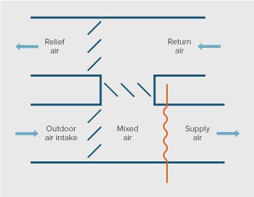
Economizer is a device that reduces cooling load on the system by directly allowing the outside air to circulate when the temperature of ambient air falls below the temperature of return air. In case the outdoor ambient air temperature almost approaches the supply air temperature it enables free cooling by turning off cooling and using ambient air as cooled supply air. Night purge ventilation can be effectively achieved using this control.
Technical description
Economizer is an intelligent automation unit which is attached to an AHU (typically in all air systems) and consists of sensors, logical control unit and actuators. It consists of an outdoor air, return air and a mixed air temperature sensor, a logic controller and motorized actuators to control the outside air and return air dampers. The temperature at the three points is constantly monitored. When the outside air temperatures fall below a set point temperature that is lower than the return air temperature then the economizer function kicks in. The economizer then gradually closes the return air dampers and more outside air is taken in directly by opening the outside air dampers thus reducing the load on the cooling system. When the temperature of the outside air falls further below which is equal to or lower than the supply air temperature then the cooling system is temporarily bypassed or turned off by using suitable controls. The outdoor air is directly used to cool the space thus enabling what is called free cooling. In regions with high humidity enthalpy economizers could be used instead of sensible air economizers as described above. Enthalpy economizers take care of both temperature and humidity and typically result in 10-15% more savings compared to sensible economizer.
Typical usage
Usage of an economizer is primarily governed by the climate of the region. An economizer is typically used where there is a substantial cooling demand and considerable days with outside air temperature lower than the designed return air temperature or supply air temperature. As it can be observed in ASHRAE 90.1 an economizer is recommended in specific climate types. In general, an economizer suits climates with temperate, mild hot and dry to moderate humid conditions and does not suit climates which are extremely hot and humid or extremely cold. California energy code called Title 24 has elaborate guidelines on the requirement, design, control and testing of economizers in non-residential buildings.
However, care needs to be taken as economizers will turn from energy savers to extra energy guzzlers if improperly installed or maintained. This happens especially when one or more components of the economizer turn faulty. The sensors, logic unit and actuators of the economizer should be tested at regular intervals to check if the economizer is operated as intended. When using sophisticated controls like economizer the HVAC systems should ideally be fully automated and regularly maintained. At times an economizer is an integrated part of the HVAC systems like in the packaged units and at times it needs to be integrated into the design of Air Handling Units.
Technical efficiency
It should always be ensured that upgraded and latest technology components should be used to make up an economizer unit. Critical parts that make up the economizer include sensors, dampers and actuators.
Stainless steel dampers are less prone to corrosion then aluminium or galvanized steel. However, since stainless steel costs much more than the others, cost analysis needs to be carried out to verify whether or not corrosion is potential problem for a given climate and if there are better ways to mitigate it. It is recommended to use directdrive actuators instead of unsophisticated linked actuators. Direct drive actuators have less number of parts between the actuator motor and the dampers and are less prone to failure. Sensors should be placed at appropriate position to accurately judge the outside air conditions and at the same time should be protected from failing. Even in relatively dry conditions use of enthalpy sensors is recommended instead of sensible temperature sensors. The control logic should enable control interlocks that integrate the economizer well with the functions of HVAC system. Safety interlocks for freeze protection should be enabled in appropriate climates. Similarly, appropriate alarm system should be integrated to indicate any malfunctioning of the system that could potentially consume more energy than required.
A recommendation from the electric energy companies, to put a cap on high demand, is to “lock the economizer in the minimum-outside-air position if an economizer repeatedly fails and it is prohibitively expensive to repair it. Although the potential benefits of the economizer's energy savings are lost, it is a certain hedge against it becoming a significant energy waster” (UPPCO, 2004).
Savings
The energy savings potential of economizers is greatly dependent upon the climate and number of operational hours of the economizer. Typical energy savings from an economizer operation is approximately 30% of the cooling energy. The energy savings are expected to be higher in milder and cooler climates and the savings gradually reduce in hot climates with no benefits in extremely hot and humid climates.
Studies show that by employing demand control ventilation energy savings of up to 40% can be obtained (Pavlovas, 2004; Becker, Bollin & Eicker, 2010).
Minimum levels of ventilation are required in space for fresh air requirements both for breathing and to maintain optimum humidity levels. Various standards and guides like ASHRAE 62.1-2010, CIBSE Guide E, describe the minimum acceptable ventilation levels (for more on ventilation see Ventilation). Ventilation in the building can be optimized effectively through a strategy known as demand control. This strategy calculates the amount of required ventilation by sensing the amount of carbon dioxide (CO2) and humidity in the space. CO2 sensors and humidity sensors are placed either in the space or in the return air duct. They measure the amount of CO2 and humidity present in the space and thereby adjust the ventilation rate accordingly. This enables reduction in the conditioned load of the fresh air by reducing the fresh air quantity and at the same time maintaining minimum fresh air levels. This can be integrated with both all air systems and also air-water/refrigerant systems. Savings should be maximised through the use of Variable Speed Drives on fans.
Displacement ventilation is suitable where lower supply air velocities are acceptable for space cooling. This leads to reduced fan horsepower and results in less energy consumption due to very low differential static pressure. Cooling supply air temperature can also be maintained higher (similarly, heating supply air temperature can be maintained lower) in displacement ventilation systems compared to overhead systems. Energy savings in the range of 20-30% are possible compared to overhead supply systems.
Technology description
Underfloor Air Distribution (UFAD) consists of a pressurized floor plenum or underfloor ducts, which force air through the diffusers located in the raised floor. This system operates through forced air convection. The return air either circulates back through a return air duct within the ceiling or a pressurized plenum, which acts as a return air path.

Underfloor systems contain single or multiple AHUs per floor. Sometimes each of the multiple AHUs is connected to a DOAS unit for fresh air and supplies only fresh air. However, systems that circulate a mix of fresh and return air are also common.
UFAD systems are suitable in spaces with relatively constant cooling/heating loads. The supply air velocity from floor diffusers is low compared to that of overhead diffusers. This results in the downsizing of fan and also in low supply airflow volumes. In addition, cooling supply air temperature can also be maintained higher (similarly, heating supply air temperature can be maintained lower) in displacement ventilation systems compared to overhead systems. UFAD systems are especially suited in spaces which anyway need a raised floor for other purposes than for HVAC. This avoids the extra costs incurred due to a raised floor.
However, UFAD systems are not suited for spaces which have constantly changing loads. Increasing the supply air velocity beyond a point could potentially create turbulence at floor level, picking up contaminants and circulating them within the space.
makes energy efficiency in buildings and appliances transparent. For investors, policy-makers and actors involved in implementation and consultancy. Learn more ...


 Buildings Guide
  Policy Guide
  Appliances Guide
  India
India South Africa